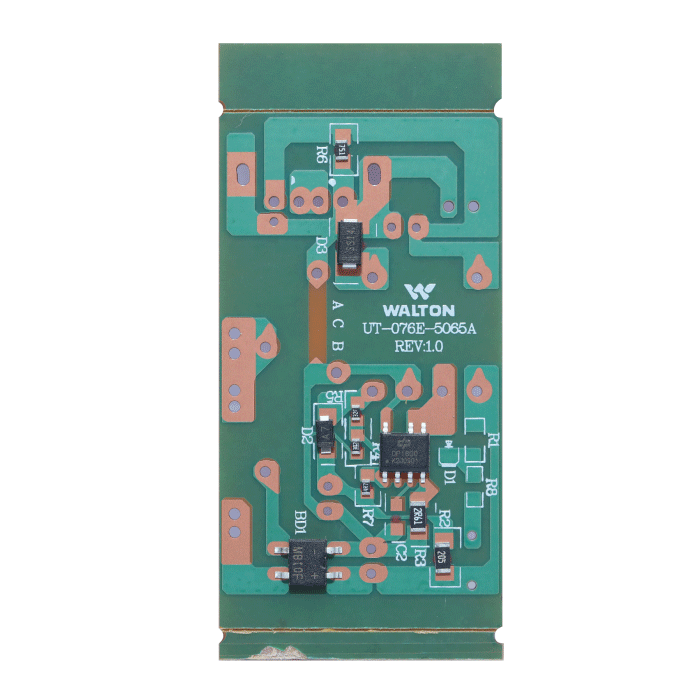
Description
“Raw Material: Printed Circuit Board (PCB), Ordinary rectifier, Bridge rectifier, DC chopper, inductor, resistor
Machines: Auto Loader, Solder paste printer, Pick and place, Reflow oven, AOI, routing, ATA jig
Process :
The production of charger PCBA (Printed Circuit Board Assembly) SMT (Surface Mount Technology) involves a series of steps and equipment. The process begins with an Auto Loader, which efficiently loads the PCBs onto the assembly line, ensuring a smooth workflow. The Solder Paste Printer then applies solder paste to the PCB pads using a stencil, ensuring precise and consistent deposition. The Pick and Place Machine accurately positions various components onto the PCB, including the Printed Circuit Board itself, as well as essential components such as ordinary rectifiers, bridge rectifiers, DC choppers, inductors, and resistors. These components play a crucial role in regulating and converting electrical currents within the charger. After component placement, the PCB proceeds to the Reflow Oven, where the solder paste is melted, creating reliable and durable solder joints. Automated Optical Inspection (AOI) systems then thoroughly inspect the PCB, checking for any defects or irregularities in the assembly. Routing equipment is utilized to create specific circuit paths and ensure proper connectivity. Finally, an ATA jig is employed to perform automated testing, verifying the functionality and safety of the charger PCBA. Through these processes and the inclusion of necessary components, the charger PCBA is manufactured, providing efficient and reliable power delivery for electronic devices.”

